
There’s two “for” tags that go along with the top cylinders to make the pegs. The top cylinders needed more work to them. I took the difference for the bottom cylinders to make the round pegs that would help hold the brick together with another. Next I made three cylinders (one for the top and two for the bottom). I resized them and used a difference tag to subtract the second one from the first one to make the opening in the brick. Tutorial Toy Brick Video Credit: mathcodeprint I made my own building brick by following along with their video. I followed another tutorial from mathcodeprint on Youtube. OpenSCAD-Project Enclosure-Create round corners with Minkowski Sum by mathcodeprint Second OpenSCAD Design
#OPENSCAD ROUNDED CORNERS CODE#
Tutorial for code help from mathcodeprint My planned changes for this box would be to go back in and do some final adjustments to the inner rim, make a matching lid, and customize the box by adding text or something else to it.Ĭode for this project and references below. Their videos have been really helpful so far so go check them out!!! I do have a tip when writing this code: Watch your brackets!!! () down to include the difference of the shape to make the inner rim of the box.
#OPENSCAD ROUNDED CORNERS HOW TO#
Site:softsolder.I followed mathcodeprint ‘s tutorial on how to make a box because I was struggling with writing code and understanding it. When I get around to doing molds, maybe I can remember what I was thinking…


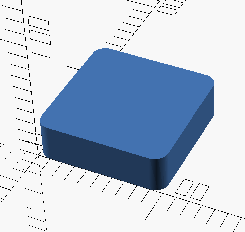
Module rcube(size=, radius=, center=true)Ĭube(size-2*radius+,0,0],center=true) Ĭube(size-2*radius+,0],center=true) Ĭube(size-2*radius+],center=true) įor(x =, y =, z = ) The (slightly modified) OpenSCAD source code: You’re supposed to temper the chocolate, but that’s probably more relevant for Fine Art molds. Shallow is good, but that conflicts with 3D printing’s crappy resolution: 1 mm = 10 layers, tops. The grayscale logo / image should have nice smooth transitions that produce suitable draft for the fine details a bare black-and-white image might not work well. If you do need draft and you don’t care about a very slightly undersized pattern, remove the internal blocks and increase the XY spacing of the lower four spheres by enough to make the draft come out right. Given a sufficiently bendy silicone mold, you might not need any draft at all. OpenSCAD constructs spheres such that they may be slightly smaller than the defined radius at the poles and, depending on their alignment, a face at the equator may reduce the outer dimension of a surrounding hull. The overall block lacks draft, because the problem it solves presumes you need a block of specific outside dimensions: it overlays three full-size rectangular blocks that define the dimensions. You could make half a dozen of them, arrange them inside a suitable printed frame, pour the silicone, and get a multi-cavity mold for better manufacturing productivity. One could slice it in half horizontally, emboss a height map defining a logo / picture into the top surface, print it out on your favorite 3D printer, maybe smooth / seal the surface a bit, define it to be a positive mold pattern, cast / pour flexible silicone around it, and get a negative mold for a pourable precious material such as, oh, chocolate. Those guys make me feel dumb, because they’re generally solving problems I can’t even imagine, but I know what to do with this solution. A discussion on the OpenSCAD mailing list about making a rectangular solid with rounded edges having different radii eventually produced this delightful result: Basic Rounded Cube


 0 kommentar(er)
